Sun Enterprise 10000 - scheda CPU
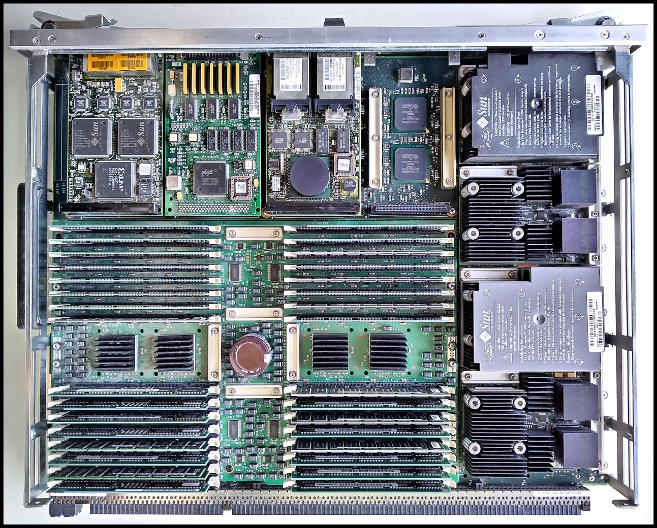
Questa è una delle schede CPU di un server Sun Enterprise 10000. Contiene 4 processori UltraSPARC-II a 400 MHz, ciascuno con 8 MB di cache (visibili sulla destra) e 2 GB di RAM, oltre ad alcune periferiche su scheda Sbus (in alto, si riconoscono da sinistra a destra un controller Ethernet a 4 porte, un controller SCSI ed una scheda Fibre Channel). Le dimensioni sono di circa 60×45 centimetri, a fronte di un peso di circa 15 Kg.
La Sun Enterprise 10000, nome in codice "Starfire", era un server high-end multiprocessore fault-tolerant derivato dal Cray Superserver 6400. Il progetto della macchina, messa in commercio nel 1997, cominciò circa un anno prima quando la Business Systems Division della Cray venne ceduta da Silicon Graphics (che nel 1996 aveva acquisito la stessa Cray) a Sun Microsystems. Da notare che il Superserver 6400, anche noto come CS6400, era a sua volta una macchina SMP fault-tolerant con CPU SPARC, nel suo caso SuperSPARC, però con un minor livello di parallelismo e ridondanza. Nel caso dell'Enterprise 10000 si trattava di un sistema dalle caratteristiche esclusive che si differenziava da tutti gli altri server Sun dell'epoca non solo per il prezzo di circa 1 milione di Dollari ma anche e soprattutto per le potenzialità e la filosofia progettuale. In sintesi era una macchina multiprocessore, da alcuni definita un po' impropriamente a parallelismo massiccio, basata su un'architettura di sistema (Gigaplane-XB) completamente ridondante e fault-tolerant a livello di interconnessione tra CPU e memoria e tra esse e le periferiche. Poteva "ospitare" fino a 64 processori che partizionabili in "domini" indipendenti, ciascuno dei quali eseguiva una propria istanza locale del sistema operativo Sun Solaris. Ogni componente del server era ridondante: alimentatori, processori, memoria. In questo modo l'Enterprise 10000 diventava una macchina resistente ai guasti e perciò particolarmente adatta ad applicazioni in cui era necessario che il server rimanesse sempre online. Ebbe difatti successo soprattutto come web server per siti di commercio elettronico (ad esempio Ebay ed Amazon) negli anni della cosiddetta "bolla delle dot-com". La modularità e la ridondanza delle sue componenti rendevano possibile la sostituzione di una qualsiasi di queste ultime senza dover spegnere l'intera macchina. Il server era controllato da un System Service Processor esterno, in genere una workstation Sun Ultra 10 o 20 alla quale si connetteva tramite un ordinario collegamento Ethernet.
Nella foto qui sopra si vede il lato del modulo CPU, talvolta chiamato "nodo", che ospita processori, memoria e schede di I/O. L'altro lato contiene regolatori di tensione e la complessa logica di interfacciamento col bus Gigaplane, realizzata con una serie di ASIC VLSI. Questi ultimi, visibili ad esempio in questa pagina: https://cray-cyber.org/old/systems/E10k_detail.php, rappresentano un elemento essenziale della macchina in quanto gestiscono la coerenza della memoria e della cache, entrambe fondamentali in un ambiente SMP a memoria condivisa. L'Enterprise 10000 era al momento della sua introduzione sul mercato il server SMP commerciale col maggior numero di CPU installabili (64). Al livello del bus Gigaplane la struttura della macchina appare come un insieme di processori UltraSPARC -architettura UPA, la medesima della workstation Ultra I- interconnessi da un crossbar 16×16, che hanno ciascuno la possibilità di accedere all'intera memoria di sistema (massimo 64 GB, ovvero 4 GB per ogni scheda CPU come questa) alla stessa banda di 12 GB/s e con la medesima latenza media di circa 500 ns.
La scheda fotografata in questa pagina è l'unica completa che sono riuscito a trovare nel corso degli anni: nella mia collezione ne ho un'altra, priva però della memoria e dei processori. Contrariamente a quanto si potrebbe pensare, tuttavia, le Sun Enterprise 10000 non sono macchine così rare, benché mi risulti che ormai ne sopravvivano solo pochi esemplari integri e funzionanti. Non so quante ne siano state vendute in Italia. Ricordo però che una decina di anni fa c'era una ditta di recupero materiali elettronici alle porte di Udine che ne aveva demolite un paio, provenienti -così mi è stato detto- dal centro elaborazione dati di una grossa banca del Nord Italia.
Vedi: https://cray-cyber.org/old/systems/E10kborn.php (breve storia dello sviluppo della Enterprise 10000).
Vedi: https://www.youtube.com/watch?v=OSprsQTsy7c (video di una Enterprise 10000 completa), oppure https://www.youtube.com/watch?v=hvI95wsKUD4.
Documentazione Sun: https://www.esocop.org/docs/Sun_Enterprise_10000_System.pdf.
Immagini del Cray CS6400: http://mbus.sunhelp.org/systems/cray/cs6400_p.htm (https://web.archive.org/web/20070928063517/http://www.filibeto.org/~aduritz/supercomputing/cray/cray-cs6400.html).
The Ultra Enterprise 10000 system is a SPARC/Solaris (UNIX-System V Release 4) scalable symmetrical multiprocessing (SMP) computer system. It is an ideal general purpose application and data server for host-based or client/server applications like online transaction processing (OLTP), decision support systems(DSS), data warehousing, communications services, or multimedia services. The Enterprise 10000 system provides the following capabilities:
- Solaris 2.5.1 and 2.6 compatible;
- internal frequency of 83,3 MHz with processors running at a clock frequency of 250 or 336 MHz;
- Gigaplane-XB interconnect: a new generation of interconnect ASICs significantly reduces the cost of the system interconnect architecture;
- Gigaplane-XB interconnect bandwidth: up to 10,5 Gbytes/sec;
- fast processing: up to 20 GFLOPS/sec;
- more reliability, availability, and serviceability (RAS) than other similarly architected systems;
- Error-Correction Interconnect: data and address buses are protected by a combination of error correcting codes and parity;
- I/O flexibility: up to 32 independent SBuses and 64 SBus slots or up to 32independent 33/66 -MHz PCI busses with 32 slots. SBus and PCI can be mixed within a system;
- high I/O bandwidth: up to 3,2 Gbytes/sec aggregate SBus bandwidth. The Enterprise 10000 system’s individual SBuses do 64-bit transfers, yielding a sustained data rate of 100 MBytes/sec per SBus;
- up to 32 I/O slots. PCI adapters are available with 32 or 64 bit data paths at a clock frequency or 33 MHz or 66 MHz;
- no single points of hardware failure: no single component prevents a properly configured Enterprise 10000 system from automatically reconfiguring itself to resume execution after a failure. This is achieved through a combination of redundancy and alternate pathing architecture. Once exception to this is the control board which requires manual intervention, following a failure, to switch to the alternate control board;
- system domains: groups of system boards can be arranged in multiprocessor domains that can run independent copies of Solaris concurrently. Each domain is completely isolated from hardware or software errors that can occur in another domain;
- dynamic reconfiguration: enables the system administrator to add, remove, or replace system components online without disturbing production usage;
- hot swapping: power supplies, fans, and most board-level system components can be exchanged while "hot," that is, while the system is online;
- scalable configurations: the Enterprise 10000 system can add memory and I/O slots without displacing processors;
- service/maintenance process flexibility: the System Service Processor (SSP) connects to the Enterprise 10000 system via conventional Ethernet, permitting system administration from a remote location. The SSP reports status information using the simple network management protocol (SNMP) protocol.
The Enterprise 10000 system is modular both in functionality and appearance. The functionality is modular in that system boards, I/O controllers, memory, and processors have no predefined position within the processor cabinet. That is, a system board can be located anywhere within the 16 slots allocated for system boards; and the I/O modules, memory boards, and processor modules can be distributed among the system boards to achieve the customer goals of either high availability, maximum bandwidth, or peak performance. The appearance is modular in that the processor cabinet has no fixed placement within a multi-cabinet configuration. Also, boards, peripherals, and subsystems are installed from either the front or the back, and all cables can egress from either of these two sides. The front of the system is denoted by the higher-numbered system boards.
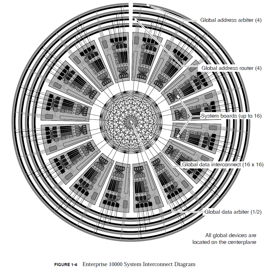
The Enterprise 10000 system boards communicate via the centerplane board. Unlike previous systems using a passive bus architecture, the Enterprise 10000 centerplane contains the Gigaplane-XB interconnect, which is comprised of active address and data routers capable of sustaining a high system board-to-system board address and data bandwidth. This high performance is realized by using address and data routers comprised of 34 ASIC chips that are mounted on the centerplane. The Gigaplane-XB interconnect has four 48-bit address buses and two 72-bit data arbiters. Each address bus is comprised of four 36-bit wide (plus ECC and parity) ASICs and one address arbiter. Each of the two 72-bit portions of the data router is comprised of six 12-bit data router ASICs and one data arbiter ASIC. The two 72-bitdata routers operate in a lock-step mode to produce a single 144-bit data bus. The address bus and data routers are partitioned into two electrically isolated, logically dependent sets consisting of two address buses and one 72-bit data router each. Each set has independent clocks, JTAG interface, and power, such that a failure of a component in one set will not affect the other. In the event that a centerplane component fails, the system can continue to operate in the degraded mode after being reconfigured using JTAG. Degraded modes use one, two, or three address buses and/or one 72-bit data router. System software must be quiescent during a configuration change. Two types of ASIC chips are used on the centerplane, XMUX and XARB. Mode select inputs to the chips enable them to operate in different applications.
The chips and their applications are:
- 16 XMUX chips are used for the four global address routers (GAMUX);
- 4 XARB chips are used to control the global address arbiter (GAARB);
- 12 XMUX chips are used for the global data routers (GDMUX);
- 2 XARB chips are used to control the global data arbiter (GDARB).
The centerplane board-to-board communication is a point-to-point interconnect with ASIC chips used for signal routing. Addresses are routed between system boards using four sets of global address multiplexer chips (GAMUX) controlled by global address arbiter chips (GAARB). Global data is routed using a 16×16 nonblocking crossbar controlled by global data arbiter chips (GDARB).
The centerplane is designed such that a single component failure will not cause a system failure. This is accomplished by partitioning the centerplane into two independent sets of components that operate together unless there is a failure. Should a failure occur, the following degraded modes of operation can be used:
- the system will operate with one, two, or three address buses. Performance degradation when operating with less than four address buses will be application dependent;
- the system can operate with one 72-bit data router. Note that the data router bandwidth is two times the available address bus bandwidth in a fully operational system. Therefore, with only one 72-bit data router the system is balanced for address and data bandwidth;
- the system will operate with one or two address buses and one 72-bit data router with a half centerplane failure;
- the system board slots can be logically isolated and effectively removed from the system.
Any system board can be hot-swapped from the system as long as the processor sand contents of memory have has migrated to other boards and the I/O has been switched to another path. The active clock board cannot be hot swapped without a system boot after configuring the clock source to the alternate clock board.
The hardware implementation in the centerplane enables the system to be partitioned into multiple domains, which can vary in size, from a single domain with 16 system boards to 16 domains consisting of one system board each.
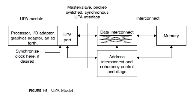
The Ultra Port Architecture (UPA) defines a separate address and data interconnect. Usually on a bus-based system only about 70% of the wire bandwidth is available for data, with the rest being used for address and control. Separating the functions lets both addresses and data each have 100% of the wire bandwidths on their separate paths, and lets the wire topology of each function be optimized differently. Snoop addresses need to be broadcast simultaneously to all the boards, while data packets can be sent point-to point. The UPA defines the processor and dynamic memory access interface to shared memory through a cache coherent interconnect. A UPA port has four interface properties. A UPA port can optionally be a master interface, must have a slave interface, can optionally be an interrupter, can be an interrupt handler.
The UPA model comprises four components: UPA ports, address interconnect and coherency control, data interconnect, memory. A UPA module logically plugs into a UPA port. The UPA module can contain a processor, an I/O controller with interfaces to I/O buses, and so forth. A UPA port as separate packet-switched address and data buses, and the address and data paths operate independently.
Enterprise 10000 System Interconnect - A combination of improvements have been implemented to increase interconnect bandwidth by tenfold over high-end bus-based systems. This amount of bandwidth is enough to keep memory latency nearly constant for data-intensive processing onf ull 64-processor configurations with some headroom leftover for faster processors in the future. Separate Address and Data Lines - The Gigaplane-XB interconnect is designed using the UPA, which defines the processor and DMA interface to shared memory through a cache coherent interconnect for a family of multiprocessor and uniprocessor systems designed around the UltraSPARC V.9 processor. The Enterprise 10000 system is the largest implementation in the Ultra Port Architecture family.
Sixteen-Byte-Wide Data Path - Relative to prior XDBus systems, doubling the data path width halved the number of cycles needed to transmit a 64-byte data packet from eight to four. Sixteen Data PathsThe Enterprise 10000 system has 16 data paths, which provide a separate data path connection to each board.
Four Snoop Paths - The Enterprise 10000 system has four separate address snoop paths that provide enough address bandwidth to match the data bandwidth. One quarter of the memory space is snooped on each of the four address buses. A snooping chip (the coherency interface controller) keeps a set of duplicate cache tags for each of the processors on its board. It snoops its address bus looking for required cache reads or invalidates.
Point-to-Point Connections - In a multidrop bus, all the processors, I/O devices, and memory modules attach to a single set of wires. As the number of connections rises, the clock rate must belowered to maintain reliability in the face of increasing electrical load. A failure of any component on the bus can bring down the entire bus, not just the connections to the failing component. Changing to point-to-point connections reduces the electrical load to a minimum, enabling a faster clock rate. Point-to-point connections enable partitioning the machine into independent multiboard domains. We call the address paths "buses" because they act like a familiar snoop-type bus for coherency transactions. Even so, the addresses are actually implemented using point-to-point switching ASICs.
Multistage Address and Data Routers - Connecting all 64 processors, 32 I/O ports, and 16 memory modules together in a giant crossbar would have been unmanageable. Instead, the Enterprise 10000 system has a two-stage routing topology based upon the physical board partitioning. Local many-to-one routers gather on-board requests, and connect them to one off-board port. A global data interconnect connects one port from each board together. Four point-to-point address buses broadcast addresses to all the boards.
100-MHz System Clock - The combination of faster logic gates, and point-to-point instead of bussed signals, enabled a design for a 100-MHz system clock. The UltraSPARC-I processor enablest he two clocks to be either a 2:1, 3:1, or 4:1 ratio. The initial Enterprise 10000 system uses a system clock of 83.3 MHz and 250 MHz processors. However, the design is capable of using a 100-MHz system clock, which will be implemented pending release of the future, faster processors.
Pipelined UPA Implementation - Typically, when the processor does a Read-To-Share UPA transaction after a load miss,the UPA protocol optimizes for the possibility that the processor will later want tomodify the data, and gives the requester exclusive access if no other processor already has the data cached. This optimization enables the processor to write the data without further interconnect transactions. On the Enterprise 10000 system, this process was modified slightly. Since the Enterprise 10000 system is a distributed, pipelined system, it cannot pipeline a conditional reply from the system of either a Read-Block-Shared or a Read-Block-Unshared fast enough for our hardware implementation of the UPA. Therefore, the Enterprise 10000 system always replies with a Read-Block-Shared. Thus, the processor will never enter the exclusive state, but instead uses the shared clean state. If a processor decides to store data, it must do a Read-To-Own coherency transaction to get the cache line into the exclusively modified state, and to invalidate any other caches copies.
The Enterprise 10000 system is partitioned into system boards interconnected by a centerplane. A single system cabinet holds up to 16 of these system boards, each of which can be independently configured with processors, memory, and I/O channels:
- four 336-MHz UltraSPARC microprocessor modules with supporting second level 4-Mbyte cache per module;
- four memory banks with a capacity of up to 4 Gbyte per system board (64 Gbytes per Enterprise 10000 system);
- two SBuses per system board, each with slots for up to two controllers for networking and I/O (32 SBuses or 64 slots per system);
- A PCI module can be used in place of the standard SBus module. The PCI module has two 66 MHz buses and each can accommodate one PCI adapter or up to 32 adapters per system.
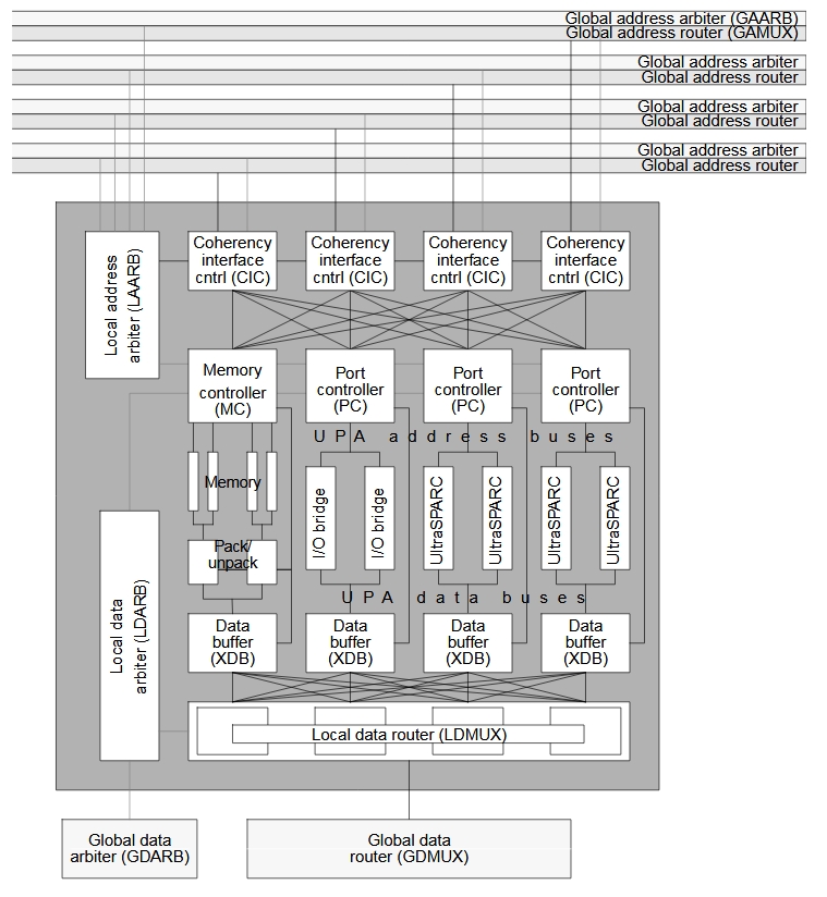
The system board is a multilayer printed circuit board that connects the processors, main memory, and I/O subsystems to the centerplane A total of 18 application-specific integrated circuits (ASICs), composed of six distinct (ASIC) types, reside on the system board. Mode select control bits in the XARB and XMUX enable them to operate indifferent applications. The two XARBs, when installed on the system board, operate in local address arbitration mode and local data arbitration mode. All four XMUX instances operate in the local data multiplexor (router) mode.
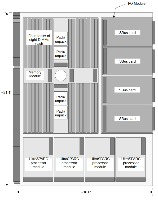
Enterprise 10000 System Board - processor side
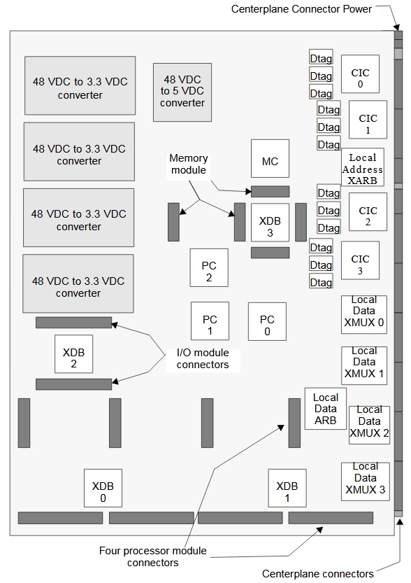
Enterprise 10000 System Board - back side
Control and Arbitration - The port controller (PC) serves as the onboard UPA controller, which is responsible for handling all UPA address and data requests to the system. The memory controller (MC) handles all accesses to main memory. All data and address arbitration on the system board is handled by an arbiter while in local data arbitration (LDARB) and local address arbitration (LAARB) mode, respectively.
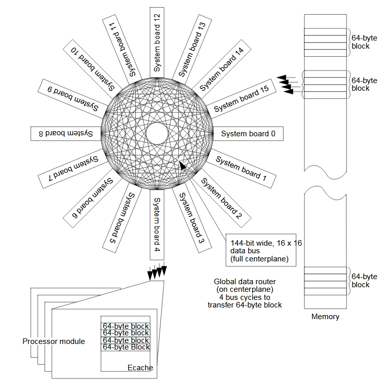
Data Interconnect - The global data router is a 144-bit-wide, 16×16, crossbar that steers data packetsbetween the 16 system boards and their caches located on the processor modules. From a hardware point of view, the global data router consists of 12 multiplexer ASICs situated on the centerplane board. As a whole, the data is organized in 64-byte packets. The system requires four clock cycles to transmit each packet. Data routing is carried out with a two-stage topology based on the Enterprise 10000 system physical board partitioning. Local "many-to-one" routers on the system boards gather on-board requests and direct them to one port (per board). The global data crossbar connects 16 system board ports together. With the 16×16 crossbar, any port can be connected to any other throughout the centerplane. The local data router (LDMUX) is used to build a system board data path of 144 bits. The LDMUX is organized as a five port by 36-bit multiplexor with each port comprised of one 36-bit input and one 36-bit output. One port connects to the centerplane global data multiplexor (GDMUX) and the other four connect to data buffers (XDBs). Data transfers between the XDBs and the LDMUX are controlled by the LDARB and either the PC (for processors) or the MC (for memory).
Address Interconnect - The Enterprise 10000 system address routing is implemented over a separate set off our global address buses. Although called address buses to convey that addresses are broadcast, the implementation is as a point-to-point router. The significance of this is that routers have more inherent reliability than does a bus, as there is only one load per driver. The buses are 48 bits wide including error correcting code bits. Each bus is independent, meaning that there can be four distinct address transfers simultaneously. An address transfer takes two clock cycles, equivalent to a snoop rate of 167 million snoops per second. Should an uncorrectable failure occur on an address bus, degraded operation is possible using the remaining buses. The four coherency interface controllers (CICs) serve as the interface between the local address buses and the global address buses. Each CIC connects to a separate global address router through one of the four global address buses. The CICs maintain cache coherency. Each CIC maintains an external set of duplicate tags (Dtags) in SRAM chips for the cache of each of the four processors on its system board. There are three SRAM chips per CIC. Each CIC also maintains a one line, internal Dtag entry for each of the two I/O boards.